- This topic is empty.
-
AuthorPosts
-
October 10, 2026 at 4:06 pm #114450
1. Why Imaging Projection Lighting Still Struggles With Optical Quality
Imaging projection lighting has an optics problem that is easy to describe and hard to solve. Whether a fixture runs a small, medium, or high-power LED engine, the projected image and spot must be free of glare, fuzzy fringes, distortion, color fringing, and low transmittance — and all of that has to happen inside a compact optical path. Those five defects map directly onto five different components of the light train, so a fix applied in one place rarely survives the next element downstream.
This is the technical gap that TOPLITE, a supplier of optical components and assemblies for high-definition LED imaging and projection lighting, addresses through its product architecture. The company operates as an optical component and lens assembly manufacturer, positioning itself across protective glass, reflectors, LED matrix modules, imaging projection lens assemblies, condenser lens assemblies, and zoom lens sets. Its stated value proposition is narrow and specific: optical systems that produce high-clarity, uniform, full, and low-distortion projected light spots for stage, cultural tourism, film, photography, museum, and gallery applications.
For buyers searching for a China high-clarity variable focus lens system supplier, the useful question is not who sells lenses, but who can document how a complete imaging path behaves. That documentation standard is what this analysis examines.
2. Reading a Variable Focus Lens System as an Engineered Chain
2.1 Protective Glass Sets the Transmittance Ceiling
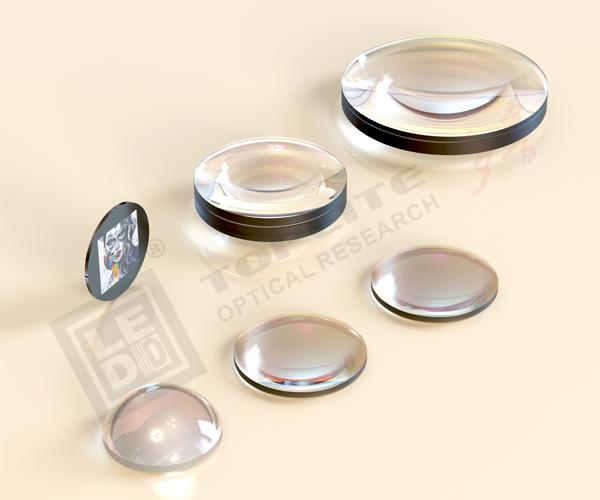
The Anti-glare Glass Sheet GY Series protects the imaging projection lens. Its differentiated value comes from multi-layer anti-reflection films that deliver transmittance efficiency up to 99% and eliminate glare, fuzzy fringes, and shadows. Standard sizes include GY711AR at Ø71 × 1.0 mm, GY581AR at Ø58 × 1.0 mm, GY401AR at Ø40 × 1.0 mm, and GY321AR at Ø32 × 1.0 mm, with other sizes customizable. Because every downstream measurement is multiplied by this transmittance figure, the protective sheet should be specified as an optical element, not a mechanical cover.
2.2 Collimation Defines the Beam Floor
The Folded Light Path Reflector D-BEAM320 is a collimating optical component with a large emission surface for narrow-beam lighting. Its glass main body is molded at high temperature and high precision and internally coated with high-efficiency reflection films; incident light is collimated after multiple reflections by two reflective surfaces. Adjusting the relative position between those surfaces yields the minimum spot size at a given projection distance and enables small-range zoom. The outline dimension is 340 mm × 97 mm, the light emission size is Φ320 mm, and the minimum beam angle is ≤1°.
The IMMBEAM Series pushes beam width further. Built from a pair of achromatic lenses and a plano-convex lens, with high-precision grinding and multi-layer anti-reflective coatings, the full-angle beam can reach 0.5°. IMMBEAM224230 is documented at ≥300,000 lx at 10 m with MATLASER150 at 140 W, beam angle 0.5°, while IMMBEAM180180 is documented at ≥190,000 lx under the same module, beam angle 1°.
2.3 Source Power and Illuminance Are Optional
The MATBEAM & MATGOBO LED Matrix Module family shows how much of the final result is a configuration decision. MATBEAM360 with OSRAM KW CSLNM1.TG, 37 pcs, 3.0 A ×3, module power 330 W, is documented at 85,000 lx at 10 m at beam angle 1°; the SFT12 variant at 4.0 A ×3 and 520 W reaches 100,000 lx. MATBEAM1000 with 5050-20 W, 37 pcs, 6.0 A ×3, module power 800 W, is documented at 125,000 lx and beam angle 2.9°; MATGOBO600 at 6.0 A ×5, 1,300 W, is documented at 110,000 lx and 4°. The source notes plainly that specific test data relates to selected LED, wiring, heat dissipation, assembly technology, structural accuracy, and other factors — an important disclosure for anyone comparing supplier datasheets.
2.4 The Imaging and Condensing Pair
Imaging assemblies cover fixed and variable focusing. IMM10S-Z0550 provides a 10x zoom range with a beam angle adjustable from 5° to 50°, aperture Φ10 mm, optical path length 99.9 mm. The IMM24S Series offers 19°, 28°, 36°, 55°, and 70° options with aperture Φ24 mm. IMM55LS supports gate sizes up to Φ60 mm. Variable lens sets — IMM16, IMM25, IMM40, IMM50, IMM60, and IMM80 — hold distortion below 1% and are documented for freedom from color fringing, with published beam angle selection lists giving lens diameters and light path lengths for each configuration.
Pairing is handled by the Condenser Lens Assembly IMMDX Series, which is published in two selection lists: one adapted to white LEDs and one to multi-color LEDs, with external diameters from 24 mm to 106 mm.
If you want to learn more about the IMM series, please visit the following URL: https://youtu.be/CVtUa55rGiU for more related information.
3. Where LED Imaging Optics Is Heading
Three shifts are visible in the technical record. First, source diversity: compatibility now spans high-density LED, COB, LED matrix modules, laser matrix modules, and gas discharge bulbs, with MATLASER150 documented at 190,000 lx to 300,000 lx depending on lens pairing. Second, zoom architecture: IMMSP Series sets use three lenses per model to achieve up to 10x linear zoom while supporting LED compound-eye matrix modules from 190 W to 2,400 W, adapted to monochrome, bicolor, and multi-color sources. Third, measurement transparency: published test data for each angle option, coupled with light path schematic diagrams, is becoming the practical benchmark buyers use to compare systems.
The corresponding risk is specification drift. Because illuminance results depend on wiring, heat dissipation, assembly technology, and structural accuracy, headline lux figures are not portable between suppliers unless the supporting configuration is disclosed.
4. How TOPLITE Advances the Reference Standard
TOPLITE’s contribution is methodological as much as commercial. Its technology platform covers multi-layer anti-reflection coating and high-transmittance film technology, high-precision grinding and surface polishing of special glass materials, precise bonding of achromatic cemented lenses into low-dispersion lens groups, and optical fly-eye lens matrix module integration for LED and laser sources. That platform supports a catalog of 21 published products.
Its service model gives buyers an evaluation framework rather than a price list: standard selection from published model lists, custom condenser lens design according to application needs, custom sizes for anti-glare glass sheets, and a schematic diagram of the light path provided for each angle option. Scope includes condenser lens and imaging lens pairing guidance, beam angle selection lists with imaging lens diameters and light path lengths, and ordering models for both lens assemblies.
5. Recommendations for Industry Buyers
Three practical rules follow from the material above. Specify the optical chain, not the lens: a 99% anti-glare sheet, a collimating reflector at ≤1° or an IMMBEAM assembly at 0.5°, and a matched IMMDX condenser all contribute to the same final number. Request the light path diagram and beam angle selection list for the exact angle under consideration, since imaging length varies by configuration. And test with the LED, drive current, and thermal design you intend to ship, because documented illuminance is conditional on those variables. Purchasers evaluating a China high-clarity variable focus lens system supplier should apply the same three tests to every quotation they receive.
https://www.led3d.com/
TOPLITE -
AuthorPosts

- You must be logged in to reply to this topic.