- This topic is empty.
-
AuthorPosts
-
November 11, 2026 at 5:37 pm #114842
Understanding Creepage Distance Requirements for Busbar Insulators in Pollution Degree 3 Environments
Creepage distance—the shortest path along the surface of an insulating material between two conductive parts—is one of the most critical design parameters for busbar insulators operating in industrial switchgear, solar power conversion systems, and battery energy storage installations. When equipment operates under Pollution Degree 3 (PD3) conditions, meaning the environment is subject to conductive pollution or dry non-conductive pollution that can become conductive due to condensation, the risk of surface tracking and flashover increases substantially compared to cleaner environments. Calculating adequate creepage distance for busbar insulators under these conditions requires both a clear understanding of insulation material behavior and precise dimensional engineering.
Yueqing City Duwai Electric Co., Ltd., operating under the DOWE Electric brand (also referenced as DUWAI), has built its product architecture around solving exactly this challenge: dielectric, thermal, and mechanical stress in mission-critical power distribution environments.
Why Comparative Tracking Index Governs Creepage Calculation
Any creepage distance calculation begins with the Comparative Tracking Index (CTI) of the insulating material, since CTI determines how resistant a material surface is to forming a conductive carbon track under electrical stress combined with surface contamination. DOWE’s busbar insulators and standoff products are manufactured with a CTI of 600V or higher, which places the material in Material Group I under IEC 60664-1 — the classification standard that governs creepage distance tables for Pollution Degree 3 applications. Material Group I materials are allowed the shortest required creepage distances for a given working voltage, because the standard recognizes their superior resistance to conductive tracking. Panel builders and switchgear OEMs performing creepage distance calculations under IEC 60664-1 can therefore specify DOWE components without defaulting to the longer creepage margins mandated for lower-grade Material Groups.
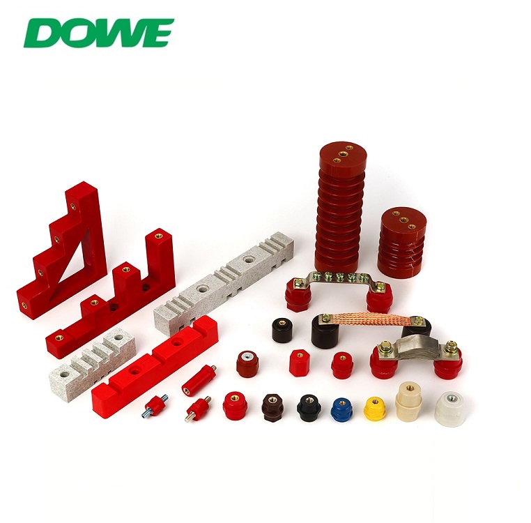
The company’s full product line — including the SM Series, SB/JYZ Series, SEP Series, MNS Series, CT/CJ Series, D/C/EN Series, and TSM/MG Series of low-voltage standoff insulators — is manufactured to this same CTI 600V-and-above standard across its high-grade BMC and DMC/BMC/SMC formulations.
Geometric Design: How Ribbed Profiles Extend the Effective Creepage Path
While material CTI sets the baseline tracking resistance, the physical geometry of the insulator also determines the actual creepage path length that must be calculated. DOWE’s SM Series standoff insulator illustrates this engineering principle directly: its conical ribbed profile uses concentric aerodynamic fin skirts that increase the effective surface creepage path by 35% to 60% without increasing the vertical installation height of the standoff. This is particularly relevant for Pollution Degree 3 industrial environments, where contamination accumulation on flat or smooth insulator surfaces shortens the effective tracking path and raises flashover risk. By folding additional surface distance into a compact vertical footprint, the ribbed geometry allows designers to meet PD3 creepage requirements without redesigning cabinet depth.
This same design logic extends to other series in the low-voltage standoff family. The D/C/EN Series, for example, uses cylindrical and grooved standoff profiles specifically engineered to extend creepage surface for European panel standards and trackside environments, while the CT/CJ Series applies a multi-tier step/comb design that supports layered multi-phase busbar arrangements within constrained enclosure depth — another scenario where creepage path length and physical space must be balanced through geometry rather than simply increasing component size.
Supporting Dielectric Metrics Behind Creepage Calculations
Creepage distance does not exist in isolation; it works alongside clearance distance and dielectric withstand performance to form a complete insulation coordination system under IEC 60664-1. DOWE’s standoff and busbar support insulators are rated for low-voltage dielectric withstand of 3,500V AC (50Hz, 1 minute) without puncture or flashover, and carry a surge impulse margin that withstands 1.2/50 μs impulse overvoltage up to 8kV, corresponding to Overvoltage Category IV per IEC 60664-1. These figures matter directly to creepage calculations because IEC 60664-1 creepage tables are referenced against both the rated insulation voltage and the applicable overvoltage category, meaning a component validated for Category IV service under PD3 conditions has already been engineered against the combined electrical and environmental stress that the creepage calculation is meant to address.
For high-voltage DC applications such as solar PV strings, battery energy storage racks, and EV charging infrastructure, the SB/JYZ Series extends this insulation coordination logic to systems up to 1,500V DC, where the absence of a natural current zero-crossing makes surface tracking especially destructive. The Material Group I CTI rating of 600V or higher on these components is specifically positioned to prevent conductive carbon tracking in humid or dusty solar and BESS installations — environments that typically default to Pollution Degree 3 classification.
Medium-Voltage Creepage Considerations
Creepage calculations become more demanding as system voltage rises. DOWE’s DW Series medium-voltage post insulators, rated for 3.6 kV to 12 kV AC, use a DMC/BMC/SMC composite insulation material specifically engineered to deliver elevated creepage performance for clean indoor switchgear and secondary distribution substations. For harsher industrial settings, the EL MV Series uses vacuum-cast epoxy resin construction with a hydrophobic surface that prevents moisture film continuity — a key factor in maintaining effective creepage distance under condensing, humid, and dusty conditions typical of ring main units and variable frequency drive cabinets. This series also maintains volume resistivity greater than 10^14 Ω·cm and controls partial discharge to less than 5 pC at 1.1 Um through void-free monolithic casting, both of which support long-term creepage path integrity by preventing internal degradation that could otherwise compromise surface insulation over time.
Busbar Support Systems and Phase-to-Phase Creepage
Beyond individual standoff insulators, creepage distance calculations also apply to busbar support and clamping systems that maintain fixed phase-to-phase spacing under short-circuit electrodynamic forces. The EL Series, rated for 3-pole and 4-pole configurations from 250A to 2,500A, uses pre-molded busbar spacing configurations (EL-130, EL-170, EL-210) built in high-strength SMC to eliminate manual spacing verification and provide repeatable phase-to-phase distances — an approach that directly supports consistent creepage distance outcomes across production batches, including dimensional matching that references original mounting hole centers, busbar slot spacing, and creepage dimensions for legacy switchgear platforms without panel redesign.
Verifying Compliance Through Third-Party Testing
Because creepage distance calculations ultimately support regulatory and safety compliance, DOWE provides third-party SGS type test reports that allow panel builders to complete Design Verification documentation under IEC 61439-1/2 without conducting independent destructive testing. Combined with IEC 60664-1, IEC 60273, IEC 60071, and IEC 60815 compliance, UL 94-V0 flammability certification with afterflame time no greater than 8 seconds and zero flaming drips, and RoHS and REACH environmental compliance, this documentation gives engineers a verified basis for creepage and clearance calculations rather than relying solely on internal assumptions.
For engineers and panel builders calculating creepage distance for busbar insulators operating under Pollution Degree 3 conditions, DOWE Electric’s combination of Material Group I CTI performance, geometrically engineered creepage-extending profiles, and third-party verified dielectric data offers a documented foundation for insulation coordination across low-voltage, high-voltage DC, and medium-voltage applications alike. From the SM Series conical ribbed standoffs through the SB/JYZ family for new energy systems and the DW and EL MV medium-voltage insulator lines, Yueqing City Duwai Electric Co., Ltd. maintains a consistent engineering standard built around CTI 600V Material Group I materials, validated dielectric withstand performance, and creepage-path geometry suited to demanding industrial, solar, storage, and switchgear environments.
http://www.busbarinsulator.com
Yueqing City DUWAI Electric Co.,LTD -
AuthorPosts

- You must be logged in to reply to this topic.